While making machines which is actuated by
stepper motors without
closed loop step motor control, you more often than not want to calibrate the stepper motors in software to make the machine move exactly as you want it to. If you tell the machine to move 10 mm in a direction, you don’t want it to move 9 mm or 11 mm.
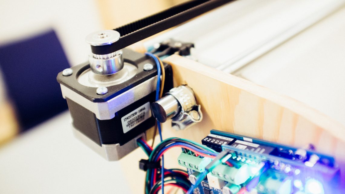
A popular stepper motor standard, the
NEMA17 motor, used together with a GT2 belt and pulley and a Grbl Arduino shield.
In motion control software (such as
Grbl) you need to specify an axis’
steps per mm or equivalent, i.e. how many steps the motor has to run to achieve a motion of 1 mm (note that this number doesn’t need to be an integer).
So, how do we find this number? Before going into that, we’re going to talk about some stepper motor basics and microstepping.
Microstepping
A very common resolution for stepper motors is 200 steps per revolution (aka. 1.8 degrees per step). We will use this resolution as an example in the rest of this post. Often 200 steps per revolution may not be sufficient to acheive the accuracy required by the men upstairs.
To increase the accuracy you can enable microstepping. This will increase the number of steps per revolution with a factor of 2n (n is an integer). Microstepping up to 8x (i.e. 8 times the full step resolution – resulting in 1600 steps per revolution in our example above) is common, but you may even find stepper systems with 256x microstepping.
One
VERY important drawback with microstepping you should take into consideration is that the holding torque drastically decreases as the microstepping factor increases. According to
oyostepper.com a microstepping factor of 8x will give you only 19.51% holding torque compared to what you get from not enabling microstepping (256x microstepping will give you as little as 0.61% of the original holding torque)!
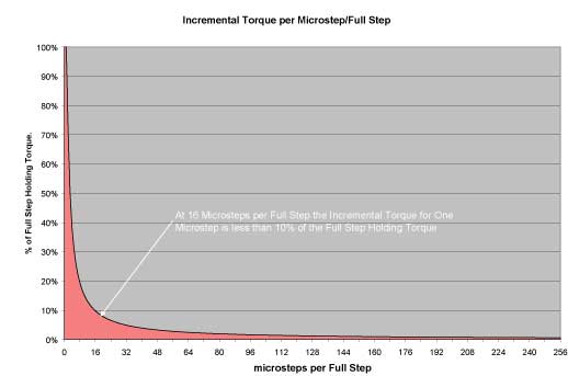
Holding torque graph at different microstepping settings (from http://micromo.com)
Thus microstepping is a dangerous double-edged sword that should be handled with great care.
Calculating Steps/mm Using Belts and Pulleys
In many of our machines we have used belts and pulleys to actuate them. These belts and pulleys come in many shapes and sizes, but one standard we have grown accustomed to is the GT2 standard. GT2 belts and pulleys come in (at least) three different sizes: 2 mm, 3 mm and 5 mm pitch.
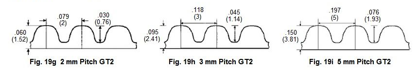
Differently sized GT2 belts (from http://instructables.com), millimeters in parenthesis.
The following equations obviously work with chains instead of belts as well, as long as you input the correct pitch. Note that these equations don’t take
backlash into account.
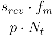
Linear Motion
Here’s a simple equation you can use to calculate steps per mm for linear motion with belts and pulleys.
srev is the number of steps per revolution for the motor
fm is the microstepping factor (1, 2, 4, 8 etc.)
p is the pitch (e.g. 2mm)
Nt is the number of teeth on the pulley attached to the motor shaft.
EXAMPLE: Using the motor in our previous example with 2x microstepping, 2 mm pitch belts and a 20 teeth pulley will give us 10 steps per mm, i.e. a resolution of 0.1mm.
A typical setup to use this equation for can be a trolley which moves linearly along an axis. One end of the belt (an open-ended one) is attached to the trolley and goes around the motor pulley, then around an idle pulley on the opposite side of the motor before the other end is attached to the trolley as well (this scheme is used both in this and this project).
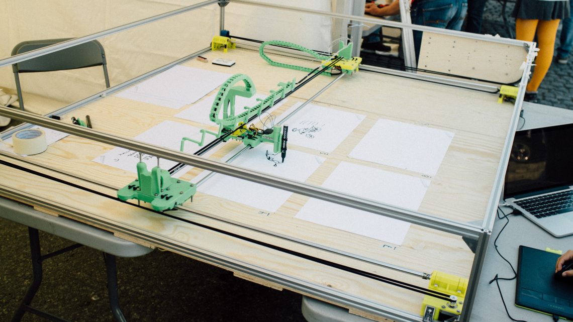
One of our earlier machines where we used stepper motors to acheive linear motion
Rotational Motion
Sometimes you want to keep things rotational. Perhaps you want to draw on a cylindrical surface or make a miniature steamroller to drive back and forth? Imagine a setup with a closed belt going around two pulleys just like the chain on a bicycle. One of the pulleys is attached to the motor shaft while the other pulley is attached to a shaft on a different axis (for instance the roller on our miniature steamroller).
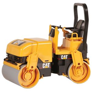
A tiny steamroller
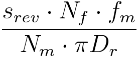
Here’s a usable equation to calculate steps/mm for this kind of setup:
srev is the number of steps per revolution for the motor
Nf is the number of teeth on the final (passive) pulley
fm is the microstepping factor (1, 2, 4, 8 etc.)
Nm is the number of teeth on the motor pulley
Dr is the diameter of the roller in our steamroller example.
EXAMPLE: Using the same motor as before with 8x microstepping, a 40 teeth pulley on the roller axis, a 20 teeth pulley on the motor axis and a 200 mm roller diameter will give us approximately 5.09 steps per mm, i.e. a resolution of around 0.2 mm.
Post-calibration
To confirm that the calibrations are correct, or just to make them more accurate, you should do some simple “post-calibrations”. This is particularly easy if you’re calibrating a drawing machine, 3D printer, a CNC machine or anything else that leaves a distinct measureable mark. To do this simple, but effective calibration process, tell the machine to move a certain distance (not too short). Measure the distance traveled and compare it to the intended travel distance. If they are identical: HUZZAH! If not, adjust your steps/mm settings with a ratio equal to the error.